Features
|
• High field strength and uniform field profile achieved via use of electromagnetic finite element
calculations in the design of the permanent magnetic assembly- • Low impedance sputtering head and standard RF connector easily match and interface with
a wide range of DC and RF sputtering power supplies. - • Easy installation with common tools.
- • Magnets are isolated from cooling water with the protective coating against corrosion to
maximize durability.
- • Sputtering source is bakeable up to 200°C
- • 1" Copper Backing Plate (EQ-CBP-1) is included.
- • Standard ¾” OD Shaft
- • Accepts 1/8” (3 mm) thick targets; 1 piece of copper target is included as standard accessory
|
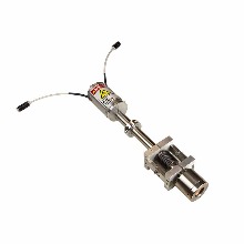
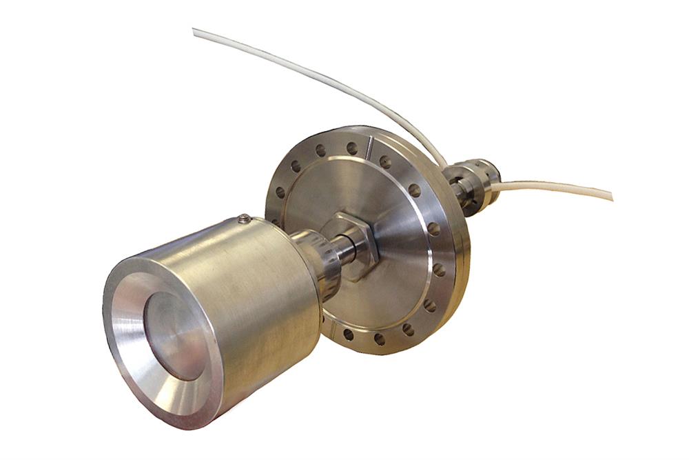
Sputtering Gun
 |
• Sputtering Head Diameter: 1.82" (46.3mm)- • Target Diameter: 1.0 ± 0.02" (25.4mm)
- • Maximum Target Thickness: 1/8" (3mm)
- • Magnets: NdFeB Rare Earth Magnet
- • Shaft Diameter: 3/4" O.D.
|
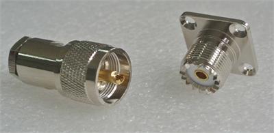
Electrical Connector

|
• Standard HN Female Connector is included (DC and RF, Picture below left )- • Optional SL16 cable Connector ( Picture below right)
- • 148 cm RF cable is recommended with extra cost (click Pic. right 1 to order)
|
Power Requirement |
• DC (Max.) 250 W- • RF (Max.)100 W
|
Cathode Sputtering Current
| 3 Amp (Max.)
|
Cathode Sputtering Voltage
| 200 - 1,000 V |
Operating Pressure Range
| ~1 mTorr to 1 Torr |
Sputtering Thickness Uniformity
Curve

|
NOTE: The Normalized Film Thickness graph above was obtained from depositing a ~200-nm thick film with a PVD HV Magnetron sputtering gun using a 1-inch Cu target. Measurements were performed using a 4-point probe in two mutually perpendicular directions (X, Y) across the wafer surface. The film was deposited onto an oxidized non-rotating Si wafer under the following conditions:
- 150 Watts DC in 10 mTorr (Ar)
- Distance of 3-inches (75-mm) from target to substrate
|
Water Cooling (Required)

|
• Flow Rate requirement: 1/2 GPM, filtered
- • Water Inlet Temperature: <20 C
- • Water hook up: 0.25" O.D. quick disconnects
|
Electrical & Mounting Fittings
|
• Electrical Connector: Standard HN type (DC and RF)- • High Vacuum Quick Disconnect is included. High vacuum Quick Disconnect with 0.75" ID
(compatible with HVMSS-SPC-1-LD). Use this component to install the HVMSS-SPC-1-LD
sputtering tool onto the baseplate (up to 1” thick) of a vacuum chamber with 1” diameter
through-hole
  
|
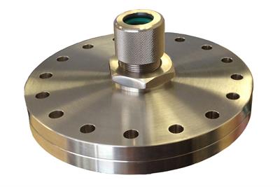
Vacuum Flange with Feedthrough
(Optional) |
6" CF flange with a high vacuum feedthrough is available upon request at extra cost. The sputtering head can be easily installed on the 6'' CF vacuum flange through the quick vacuum clamp. The height position of the sputtering gun can be manually adjusted inside the vacuum chamber.
|
| Overall Length | 14 inches |
| Net Weight | 3 lbs |
Tilt Assembly |
• The sputtering head can be tilted +/- 45 degrees for adjusting the incidence angle of
bombardments to improve the sputtering yield.- • Scribe lines on the tilt assembly offer precise angle adjustments.
  
|
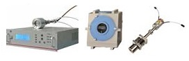
Optional Accessories |
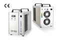
• Digital Temperature Controlled circulating Water Chiller with 6 Liters Tank, 16L / min Flow is
available at extra cost, please order separately.- • MTI offers various sputtering accessories designed to be used with the HVMSS-SPC-
1 magnetron sputtering gun for customers interested in creating custom DIY Magnetron
Sputtering Coaters:
|
Operation Instructions | |
| Warranty | One year limited with lifetime support |
Info on Sputtering Coating
|
DC Sputtering
Also known as Direct Current Diode Sputtering and it is the most basic type of sputtering. Ionized Argon cations are accelerated towards the cathode with the use of a negative bias voltage. Upon the collision of Argon with the cathode (where the target material is placed), species from the target source are ejected and subsequently get deposited on the substrate.
RF Sputtering
It is ideal for use with electrically insulating or dielectric target materials or substrates such as ceramics. It allows a much lower Argon pressure than the DC counterpart (1-15 mTorr vs 100 mTorr) to be used, which in turn reduces the concentration of gas impurities and in the chamber while also improving the deposition's line of sight due to fewer gas collisions.
Magnetron Sputtering
This sputtering feature greatly increases the sputtering rate by concentrating ions and electrons in a confined region above the cathode. By trapping electrons near the target material using a magnetic field, the ionization of Argon is greatly increased while also further lowering the gas pressure to 0.5 mTorr to improve the deposition's line of sight even more.
The characteristics above offer improved deposition rate decreased impurities of coatings and allows for operating under lower substrate temperatures in depositions. This type of sputtering can be used in conjunction with a DC or RF power source.
Useful Tips for Improving Sputtering Results
- • Keep the specimen chamber of the sputtering coater clean at all times
- • Isopropyl alcohol is preferred for cleaning metal surfaces (including targets)
as acetone takes longer to outgas and could reduce vacuum performance
- • Always isolate the rough vacuum pump from the specimen chamber to
prevent the backflow of pump oil (hydrocarbons) into the chamber.
This prevention of chamber contamination is normally achieved by shutting
off the valve that connects the coater unit and the vacuum pump
- • Rotary substrate holders can be used to improve the evenness of coating
on specimens with irregular surfaces
- • Coating uniformity can be further improved by using high purity gas and
targets. Ideally, the targets used should be at least 20% larger in diameter
than the substrates
|